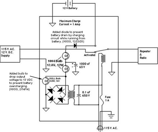
for RRARS Repeater WØGS
Joseph A. Counsil - KØOG, 21 July 2001
(Installed and tested at repeater site: 2 September 2001)
(Updated 23 December 2020, K0OG)

NOTES:
With the repeater under full load during transmit, AND the remote-base unit activated and in transmit mode (an approximate 10-amp total load current), the 110-Volt AC power was removed thus causing the backup power controller to switch to battery supply. It was noted that there was no interruption of transmission by either transmitter. Numerous interruptions were implemented during this worst-case loading condition, with no disruption of service noted. Battery voltage was monitored during this worst-case loading condition, and the battery output was observed to drop to approximately 12.7 Volts. (The batteries were not fully charged at that time, but had only received a small trickle charge for a few hours.) Additionally, with the repeater in receive condition the power was interrupted numerous times, with the observation that there was no interruption of service. The conclusion is that the repeater and remote-base radio are both sufficiently internally buffered, and the power controller relay is fast enough, that there is not sufficient supply-voltage dropout to interrupt service or reset the RI-210 repeater controller.
The detailed specifications of the two batteries are not known, so for the purpose of this calculation I will assume that each battery has a capacity of 100 Amp-hours. I will further assume that the repeater will be functional until approximately 50% of the battery capacity remains, at which point the output voltage sags below the repeater operational limit. (NOTE: At some point prior to repeater shutdown due to voltage sag, the repeater will automatically reduce its output power to approximately 10 Watts.) Assuming full output power of the repeater plus remote-base unit, the total output power will be 75 Watts (25 Watts for the repeater transmitter and 50 watts for the remote-base transmitter). Assuming an approximate 50% efficiency for the transmitters, the total load power will be approximately 150 Watts. This would translate into a load current of approximately 150 Watts/12 Volts, or 12.5 Amps (worst-case). With a battery of 200 Amp-hour capacity, and allowing for 50% usage, that leaves 100 Amp-hours of usable capacity. Therefore, the 100% duty-cycle time of operation would be 100 Amp-hours/12.5 Amps, yielding 8 hours of transmission time (worst-case). Even in an emergency-operation condition, the duty cycle would be something like 50%, thus yielding a servicable time (worst-case) of approximately 16 hours. Therefore, even in emergency operations, the repeater would provide an approximate full day of operation from battery-backup power. Under normal non-emergency, non-remote-base operation, the load would be less than 4.2 Amps, thus yielding a 100% duty-cycle transmission time of about 23.8 hours. Presuming a relatively busy duty cycle of 25%, that would yield about 95 hours (or approximately 4 days) of operational time from the batteries. It is therefore conceivable that in a power-loss situation, with careful use of the repeater, it would be possible to operate the repeater for as long as a week, and still be able to carry a reasonable amount of priority traffic. |
Web master contact: rrars@rrars.org